Most polymeric materials are extruded at least twice in their lifetime, rst through a pelletising die after the reactor and then for nal shaping.In simplest terms, screw extruders are polymer pumps with the capacity to melt the material which they are fed. Screw extruders comprise one or two Archimedean screws rotating in a heated barrel.
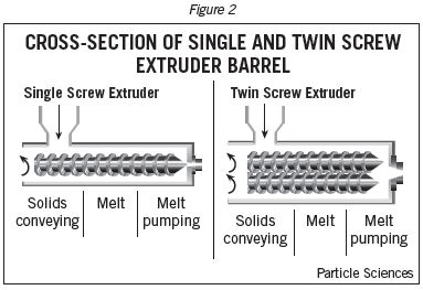
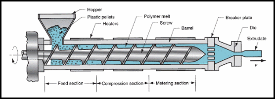
The single screw extruder (SSE) is the workhorse of the plastics industry. Polymer resins in the form of pellets, powders or fakes from a hopper to the gap between a rotating screw and a heated barrel. The depth of the con- veying channel in the screw is contoured from large to small in the ow direction, to account for the density change from the particulate solid feed to the molten polymer extrudate, and for pressure development. The SSEs normally have diameters between 25 and 250 mm, and length/diameter ratios between 20 and 36. Usual rotation speeds range from 20 to 150 rev min . A 60 mm diameter machine may deliver up to 200 kg , while a 150 mm diameter machine can exceed 1000 kg.
In the first, or solids conveying, zone of the extruder, the solid polymer particles are compacted together in the screw channel by the rotating action of the screw to form a solid bed of material.At the start of the next extrudersection, the plastication (melting) zone, barrel heaters cause a thin film of molten polymer to form in the gap between the solid bed and the barrel wall. The melt lm is subjected to intense shearing in the thin gap, and because of the extremely high viscosities of molten polymers, high rates of viscous dissipation result. The generated heat melts the solid bed within a short distance of the start of melting. In the last zone of the extruder, the metering section, the polymer melt flow is stabilised in the shallow screw channels, and nally the material passes out through the die at the end of the machine.
Pressurebuildupowing to frictionalforcesin the solids con- veying section of the screw has been modelled by Darnell and Mol (along with some more recent research ) on the basis of force and torque balances, which result in an exponential expression. For forward motion of the solid bed, the friction coeffcient must be larger on the barrel than on the screw. Screws have polished surfaces. The barrel surfaces are sometimes intentionally roughened (as in grooved barrels).
To improve the mixing capabilities of single screw extruders, various types of mixing devices have been developed. Most prominent among these is the Maddock (or Union Carbide) mixer, in both straight and spiral variations.These devices are normally located at the downstream end of a screw, and improve melt quality by reducing temperature non-homogeneities in the polymer stream and increasing the dispersion and distribution of additives. Used increasingly in the extrusion industry are barrier screws and grooved barrels. Barrier screws have a secondary screw ight in the melting section of the screw, which serves to segregate the solid bed from the molten polymer. By independently controlling the dimensions of the solids and melt channels, the melting process can be accelerated and made more stable, there by increasing the extruder output and melt quality. Grooved barrel extruders feature axial
grooves or slots in the part of the barrel immediately following the feed throat. The grooved barrel can signi cantly enhance feeding of resin pellets and flakes, and thereby sharply increase the output of the extruder above the drag ow output of equation.
Twin screw extruders(TSEs) are extruderswith two screws of the same diameter, which turn side by side within the extruder barrel at the same speed. In recent years, twin screw extruders have come into increasingly wider use in applications such as mixing, blending, compounding of thermoplastic polymers with additives, devolatilisation and reactive extrusion.The TSEs offer greater control over residence time distribution (RTD) and mixing than that of single screw extruders, and have superior heat and mass transfer capabilities. The disadvantage of TSEs compared with SSEs is their signi cantly higher capital cost.
There are three major classes of twin screw extruders: corotating intermeshing, counter rotating intermeshing and counter rotating non-intermeshing. The screws are made up of conveying, kneading block and mixing sections. The screw design is frequently modular, which allows for a nearly unlimited number of possible screw con gurations. Kneading blocks comprise several discs staggered at an angle to one another, the motion of which causes intense shearing and has a chopping effect on the material stream. Most of the dispersive mixing (melt homogenisation and solids breakup) and melting that occurs within the extruder takes place in kneading blocks.
Corotating intermeshing twin screw extruders are the most common type of TSE. These machines have the feature that their screws are self-cleaning,owing to their special design.This leadsto narrower RTDs in these extrudersthan in SSEs, making them particularly attractive for use with thermal and shear sensitive materials, as there are no dead spots in which material can collect and degrade. Large twin screw extruders can rotate at more than 1200 rev min RPM with outputs of more than 10 tons/h.


Hello there! I could have sworn I’ve visited your blog before but after
browsing through a few of the articles I realized it’s new
to me. Anyhow, I’m definitely happy I stumbled upon it and I’ll
be book-marking it and checking back regularly!
It’s an awesome piece of writing in support of all the internet people; they will obtain advantage from it I am sure.
Write more, thats all I have to say. Literally, it seems as though you
relied on the video to make your point. You clearly know
what youre talking about, why waste your intelligence on just posting videos to your weblog when you could be
giving us something enlightening to read?